Top Mold Design Services for Better Part Quality
Mold design services determine whether an injection molded part launches cleanly or becomes a cycle of flash, warp, sink, and engineering changes. For industrial OEMs, the real value is not the CAD file alone. It is the link between part geometry, resin behavior, tool construction, and process validation. That link solves the core problem: turning a printable model into a repeatable production part with stable quality, cost, and lead time.
What are mold design services in injection molding?
Mold design services are the engineering workflow that turns a 3D CAD model into a production-ready tool; Autodesk Moldflow and CMM inspection connect that workflow to measurable part quality.
A strong mold design scope usually includes DFM, gate selection, cooling layout, venting, ejection, parting-line strategy, shrink-rate planning, and tool construction details. The point is simple: if the mold design is wrong, even a capable press and a good resin will struggle.
A common misconception is that mold design is just tool CAD. It is not. It is a production strategy. The design must match the selected polymer, the target press tonnage, the part tolerance stack, and the expected annual volume. If one of those inputs changes, the mold concept often needs to change with it.
Which mold design decisions most affect part quality?
Gate placement, cooling layout, and draft angle have the biggest quality impact; PP and glass-filled nylon react very differently to those choices.
Part quality is shaped long before first shots. Wall thickness transitions influence sink and differential shrink. Parting lines influence flash and witness marks. Ejection layout influences scuffing and deformation. Cooling layout often decides whether the part stays flat or walks out of tolerance.
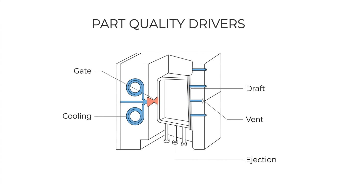
The highest-impact decisions usually include:
- Draft angle: Typical starting points are 1° to 2° per side, with more draft needed for textured surfaces.
- Gate location: Balanced filling lowers weld-line severity, cosmetic variation, and pack imbalance.
- Cooling circuit layout: Uniform thermal control cuts warpage risk and shortens cycle time.
- Venting and shutoffs: Good venting prevents burns and short shots; good shutoffs reduce flash.
- Ejection strategy: Pin, sleeve, or stripper design should match part geometry and surface requirements.
Pro tip: a cosmetic defect is not always a polishing problem. Many gloss shifts, blush marks, and witness issues start with fill pattern, venting, or pack pressure.
What mold design service partners should industrial OEMs shortlist?
The best partner is usually an integrated one; Metro Custom Plastics and Autodesk Moldflow-style simulation reduce handoff risk between design, tooling, and production.
For most industrial programs, the right partner depends on how much ownership is needed after tool approval. If the same team handles DFM, tool build, sampling, and production, feedback loops are faster and launch risk drops.
- Metro Custom Plastics: Best fit for OEMs that want DFM, in-house tooling, molding, assembly, and logistics under one roof. The integrated model supports tooling in roughly 4 to 12 weeks and production in about 2 to 3 weeks, with capability up to 64 cavities and 650-ton presses.
- Independent mold design bureau: Good for early concept work or when an OEM wants design-only support, but the handoff to the toolmaker can create revision risk.
- Regional tool shop: Strong fit when local access matters and the program is tool-centric, though production validation may rely on outside molding partners.
- Offshore tooling supplier: Can reduce upfront tool price, but response time, ECN management, and transfer risk often become the trade-off.
- Large global molder-toolmaker: Useful for multinational footprints and very high-volume programs, though mid-volume industrial jobs may get less process attention.
How should a DFM review for mold design services work?
A solid DFM review starts with geometry, not steel; NX and SolidWorks files should be checked against tolerance, resin, and machine limits before the tool concept is approved.
Step 1 is part geometry screening. The team reviews wall thickness, ribs, bosses, undercuts, draft, shutoff feasibility, and cosmetic surfaces. If a rib is too thick, then sink risk rises. If the part has a deep texture, then draft usually needs to increase.
Step 2 is process fit. The resin family, shrink rate, shot size, clamp tonnage, and gate strategy are checked against the target press. This is where many avoidable problems surface. A print can call for tight tolerances, but if the chosen polymer has wide shrink variation, then the tolerance plan may need to move to steel-safe tuning, inserts, or a different resin.
Step 3 is tool-risk review and signoff. The toolmaker, molder, and OEM should agree on critical-to-quality dimensions, sample quantity, inspection method, and expected defect limits. Pro tip: tighter tolerances do not always make the part better. They often raise cost and tool complexity without changing function.
How does mold flow analysis improve gate placement and warpage control?
Mold flow analysis predicts filling, packing, and cooling behavior before steel is cut; Autodesk Moldflow and Unigraphics NX are common tools for this work.
Step 1 is simulation of fill, pack, cool, and warp using the proposed resin and part geometry. This estimates pressure demand, weld-line location, air traps, sink tendency, and differential cooling.
Step 2 is scenario testing. Engineers compare gate locations, runner sizes, wall adjustments, and cooling concepts. If one gate location reduces pressure but creates a visible weld line in a cosmetic zone, then the team has to choose whether appearance or lower injection pressure matters more.
Step 3 is conversion to tooling actions. The output should drive gate size, vent placement, water-line routing, and steel-safe areas for tuning. A common mistake is treating simulation as proof. It is not. It is a forecast that should be validated during sampling with gate freeze, cavity-balance, and dimensional studies.
How do hot runner and cold runner mold designs compare for cost, waste, and quality?
Hot runners cut runner scrap and support higher output; cold runners cost less upfront and are simpler to maintain. Husky and Mold-Masters are common market benchmarks for hot-runner systems.
Hot runners make sense when material cost, annual volume, and cycle stability justify the added manifold and thermal-control complexity. Cold runners remain strong for lower-volume work, frequent color changes, or resins that are sensitive to long residence time.
Factor Hot runner mold design Cold runner mold design Upfront tool cost Higher Lower Material waste Lower, often much lower Higher due to runner scrap Startup complexity Higher Lower Maintenance skill needed Higher Lower Best fit High-volume, stable demand Lower volume, simpler launches Common risk Thermal imbalance, drool Scrap, regrind limits Common misconception: hot runner is not automatically the premium choice. If demand is modest or color changes are frequent, a cold runner may produce a better total cost picture.
How do single-cavity and multi-cavity mold designs compare for consistency and throughput?
Single-cavity tools are easier to validate; multi-cavity tools deliver far more output but demand tighter balance control. Cavity-balance studies and tip-delta checks become essential as cavity count rises.
If annual volume is uncertain, single-cavity molds lower capital risk and simplify process development. If demand is stable and high, multi-cavity molds lower unit cost by spreading cycle time across more parts.
Factor Single-cavity Multi-cavity Initial tool cost Lower Higher Process setup Simpler More complex Cavity-to-cavity variation Minimal by design Must be managed Throughput Lower Much higher Best fit New programs, low to mid volume Stable high volume Key engineering focus Part quality Balance and consistency For industrial programs, family molds can look attractive, but they introduce packing and fill imbalance when part sizes differ. If one cavity fills early and another late, then both quality and scrap can suffer.
What should a mold sampling and qualification plan include?
A good qualification plan proves the tool and the process together; RJG decoupled molding and CMM inspection are practical anchors for that proof.
Step 1 is incoming tool review and safe startup. The team checks mechanical function, water circuits, hot-runner zones, vent condition, and steel match before production-intent sampling begins.
Step 2 is process-window work. That usually means water-flow recording, gate freeze study, fill-balance review, and pressure or speed linearity checks. If the gate freezes too early, then pack effectiveness drops and sinks may appear. If cavity balance is wide, then one cavity can pass while another drifts.
Step 3 is quality validation. Visual inspection alone is not enough. Critical dimensions should be measured on a CMM or optical system across multiple shots and, for multi-cavity molds, across multiple cavities. Pro tip: a tool is not qualified because it makes a few good parts. It is qualified when it makes good parts predictably inside a documented process window.
Why does early supplier involvement reduce mold revisions and launch delays?
Early supplier involvement cuts revision loops; Metro Custom Plastics and Texas-based tooling teams can flag gate, cooling, and machine-fit issues before steel is cut.
This matters because most expensive changes happen after tool release. If engineering freezes the part before the molder reviews shutoffs, ejection, or moldability, then the program may inherit avoidable inserts, weld-line movement, or cosmetic compromises.
The benefit is speed, but not just speed. It is cleaner decision-making. If a boss location blocks cooling, then warpage risk should be discussed while geometry is still flexible. If the part requires a 650-ton press because of projected area and cavity count, then the sourcing team should know that before the RFQ closes.
How should resin selection and shrink rate be handled during mold design?
Resin selection should be locked before final tool approval; Sabic PP and DuPont nylon grades behave differently in shrink, moisture response, and gate sensitivity.
The mold cannot be designed well around a vague material note. Unfilled PP may process easily but can move more in shrink. Glass-filled nylon improves stiffness and heat resistance, but it can increase tool wear, anisotropic warpage, and surface read-through.
A useful rule is straightforward. If the part’s function depends on dimensional stability, then shrink behavior matters as much as tensile strength. If chemical exposure, UV, or pressure is severe, then resin selection may override cosmetic preferences or tool simplicity.
Pro tip: a resin datasheet is only a starting point. Published shrink ranges are broad. Final shrink values should be refined during sampling because gate style, wall thickness, pack pressure, and mold temperature all shift the result.
When should OEMs move mold design services and tooling transfers back to the U.S.?
Reshoring makes sense when speed, revision control, and tool support matter more than the lowest initial tool price; Texas and the central U.S. offer practical logistics advantages.
OEMs usually revisit sourcing when one of three things happens: engineering changes accelerate, supplier response slows, or mold maintenance becomes hard to manage across time zones. A transferred mold can run well in a new plant, but only if requalification is treated as an engineering project rather than a shipping event.
The trade-off is clear. Offshore tooling can lower initial spend, while U.S.-based design and transfer support often lowers total program risk. If the program needs frequent ECNs, rapid spare components, or short replenishment cycles, then domestic mold design support often wins on total cost, not just convenience.
Keywords:
mold design services